
Generate Pit Contours
To access this screen:
-
Design ribbon >> Pit Modelling >> Pit Contours.
Note: This task is part of Interactive Pit Design functionality.
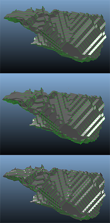
This panel is used to create smooth contours around a model containing pushback information.
The intention of this function is to minimise the need to manually digitise strings around model sections. These contours can be used in other pit design processes such as the Ramp Layout task, where they can be used as a starting point for creating pit shells for the road tester, or as constraint strings in the Auto Design task.
Generating pit contours is a two-step process.
-
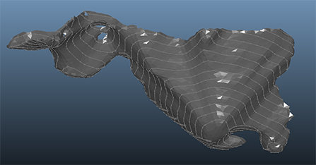
Create a wireframe shell from a surface or planning model.
-
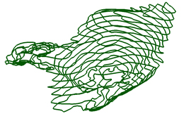
Use the wireframe shell as a canvas for generating regular contours, with options for using spline geometry so the resulting contours are practical.
Having these as two distinct steps allows the wireframe shell to be inspected and, if necessary, recreated or further processed before being used to generate the contour strings.
Use this panel in conjunction with the Pit Data control bar. It is recommended that you float the Pit Data bar so that both it and the Pit Contours task are visible at the same time, providing access to the DTM Shells and Shell Contours objects for visibility control and formatting.
Creating Practical Contours
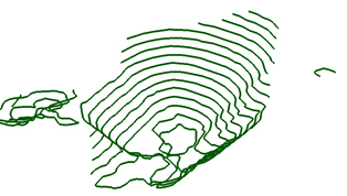
Automatically generate the bench toe strings for each bench using bench design parameters. Contours may, for example, represent the boundaries formed by the pushback bench toe perimeters. They can either be generated according to fixed elevations from a starting height, or you can use the benches that are already defined within your project.
Data Management With This Command
Note: Surface data created by this task will be stored within the current project database when the task is saved. 2 objects will be converted to physical files; the pit shell DTM and the contour strings object.
Generate Surface Options
The following options are available for generating the shell surface (referred to within Studio OP as the Shell DTM).
-
Generate from Model – This option is only displayed if a model has been assigned to the selected pit, and that model includes either an Optimised phase, Mining Phase, or LG phase field. Contours are generated from an idealised pit shell wireframe created using isosurfaces derived from the model. If this option is chosen, an isosurface will be generated using one of the following data scenarios:
-
If phase information has been defined manually (using the Define Phases task, selecting the Manual option, then defining each phase name needed to represent the ultimate pit) – A Value drop-down is provided to select the key field value for the model used to construct an isosurface. Unique values found in the phase attribute of the planning model are listed in the Value drop-down list. You are alerted if more than 500 values are detected.
-
If phase information has been defined automatically (using the Define Phases task and selecting the Use Model option) – No Value drop-down list is shown because the phase and key field value are already known. The wireframe is created around all cells with a Phase/Keyfield value less than or equal to the specified Phase value (Pit specification). The upper surface of the wireframe is automatically removed to leave just the lower pit shell.
-
-
Show top surface – By default, this check box is disabled, meaning a phase shell surface will not be generated over the pit void. If enabled, the phase shell from which contours will be generated will be a closed volume.
-
Generate from Contours – Use existing contour strings to create a surface that can then be used to generate regularised contours.
-
Import – Import a surface for use as the shell surface.
-
Generate – Generate the shell surface using the selected options.
Note: Contours will be generated from the wireframe specified in the Generate Surface section. Although these would normally have been generated as an earlier step within this command, it’s possible to generate contours from existing wireframes by selecting them in the Generate Surfaces box before performing the final contouring calculation.
Generate Bench Contours Options
Use these options to generate contour strings from the generated surface.
-
Fixed Elevations – Generate contours at fixed elevations from a starting height.
-
Benches – Generate contours using benches already defined within your project.
-
Use splines – Use spline geometry to create smoother contour strings.
-
Bezier – Use Bezier spline geometry.
-
Interpolated Bezier – Use interpolated Bezier spline geometry.
-
Interpolated Parabolic – Use interpolated parabolic spline geometry.
-
-
Subsample – Control subsampling behaviour for contour generation.
-
Smooth – Apply smoothing to generated contours.
-
Simplify Contours – Simplify generated contours.
-
Presimplify Contours – Presimplify contours prior to other processing.
-
Generate – Generate the contour strings.
Note: Interpolated splines can often produce a lot of points in areas of relatively little curvature, as spline points are evenly distributed between input points. The Simplify Contour option can be used to clean up these results and only keep points in areas of greatest curvature.
Activity steps:
-
Display the Generate Pit Contours screen.
-
Select a Pit and Phase from which to generate contours.
-
In the Generate Surface section, choose how to create the shell surface, for example Generate from Model or Generate from Contours.
-
Another option is to simply Import contour strings.
-
-
If available, choose a Value for the phase or key field required for surface generation.
-
If required, enable Show top surface.
-
Click Generate to create the shell surface.
-
In the Generate Bench Contours section, choose whether to generate by Fixed Elevations or Benches.
-
If required, enable Use splines and choose the spline method.
-
If required, apply additional processing options such as Subsample, Smooth, Simplify Contours, or Presimplify Contours. See above for more details on these options.
-
Click Generate to create the contour strings.
-
Save the task to store the generated surface and contour strings.
-
Save your project.
Related topics and activities